From planning and design to implementation and completion, a project engineer does it all!
Continue reading5 Questions to ask a Control Systems Engineer
From planning and design to implementation and completion, a project engineer does it all!
Continue readingDay in the Life of a Project Engineer at M.G. Newell
From planning and design to implementation and completion, a project engineer does it all!
Continue readingDay in the Life of a Panel Builder at M.G. Newell


Lean Transformation of a ULT line

One of our customers was looking for help to improve the efficiency of their Ultra-Low Temperature (ULT) freezer line. They were performing a lean transformation of the line. The demand for ULT freezers doubled in 2020 because manufacturers used these freezers to store COVID-19 vaccines.. Pfizer recommended that their vaccine be stored at -70 Celsius, while Moderna and Johnson & Johnson recommended storage temperatures of -20 to 8 Celsius. One of the Manufacturing Engineers was leading a mission-based team to streamline the ULT line.
Ultra-low temperature (ULT) freezers are essential to any lab environment, as they play a critical role in helping to ensure the safe storage of precious samples. ULT freezers operate within the −50°C to −80°C range and store a wide range of analytes and products, from biospecimen samples to enzymes and drugs

The engineer requested Newell Automation’s support to improve the throughput of the foaming process. One of our Senior Controls Engineer and our Account Manager reviewed the operation of the foaming jigs. They determined that we could improve the process by replacing the two-hand machine control with a momentary push button control and upgraded safety devices. We proposed installing vertical light curtains on the loading side of the three foaming jigs. We also reprogrammed the PLCs to sequence the machine with a single momentary push button press. The customer accepted our proposal. We scheduled and completed the work over two Saturdays to avoid disrupting their production schedule.

This upgrade has improved Takt time by allowing the operator to perform other tasks while the machine is cycling. The upgrade has also improved machine safety. The light curtains act as an emergency stop and ensure that no one, including another operator, enters the hazardous area while the machine is actuating.
How to select a Control Panel builder

Depending on your process, a control panel may be small – designed to control a simple batching process – or complex – designed to control several loops and integrate various pieces of equipment in various locations around your plant. As such, these panels can house an increasing array of devices. In addition, you may want to plan for a future expansion.
When selecting a vendor to build your control panels, it is wise to do some homework and check out their work. We’ve put together a few Frequently Asked Questions to help guide you through the process of selecting an automation company to build your control panel.
Are they UL® Certified? Do they use UL components?
UL is a global, independent safety science company with over 100 years of expertise in safety solutions. UL standards encompass their extensive range of safety research and scientific expertise. Most control panels fall under the UL-508 specification. This requirement covers industrial control panels intended for general industrial use and operating from a voltage of 1000 volts or less.
Within this standard, UL-508A is the UL standard for the construction of Industrial Control Panels. It provides guidelines to panel builders on various issues including proper component selection, wiring methods and calculation of short circuit current ratings. A panel that carries the UL-508A listed mark means that the panel, it’s electrical components and construction meet UL-508A standards.
Electrical inspectors look for this mark as evidence of third-party certification. This is important to a local municipal inspection authority as well as the panel purchaser. It shows that the panel is compliant with acceptable safety standards.
Do they have other certifications?
Other than UL Certifications, most engineers and panel builders also have other industry certifications. Other organizations include CSIA – the Control System Integrators Association and ISA – the International Society of Automation. Both organizations perform independent audits on the panel builder and/or the company and provide a non-biased, objective assessment.
CSIA Certified companies have demonstrated through an independent audit that they adhere to CSIA’s comprehensive Best Practices. Key areas covered include not only project management, system development and quality assurance, but also covers the company’s financial health, human resources and marketing and business development.
![]() ISA certifies a technician’s skills. Through their Certified Control Systems Technician (CCST) program, they provide an objective assessment and confirmation of a technician’s skills. ISA’s three levels of CCST certification require differing degrees of technical experience, education, and training. CCSTs calibrate, document, troubleshoot, and repair/replace instrumentation for systems that measure and control level, temperature, pressure, flow, and other process variables.
ISA certifies a technician’s skills. Through their Certified Control Systems Technician (CCST) program, they provide an objective assessment and confirmation of a technician’s skills. ISA’s three levels of CCST certification require differing degrees of technical experience, education, and training. CCSTs calibrate, document, troubleshoot, and repair/replace instrumentation for systems that measure and control level, temperature, pressure, flow, and other process variables.
Do they keep their panel building area clean?
Keeping your panel building facility clean may sound like a no-brainer, but the benefits of a clean facility go beyond simply clean floors. The most important component of any work environment is its people. By providing a clean and hygienic workplace, businesses can make a significant positive impact on the health and safety, productivity and satisfaction of employees.
Studies have shown that employees in a clean facility are 12% more productive. What would this look like in a panel building shop? It means:
- projects are clearly organized and in their own workplace
- components are labeled and stored with the correct project
- tools and other supplies are clearly labeled and easily accessible
- trash and other non-used supplies are removed from the work area regularly
- dust, dirt and debris are reduced that could cause a fault within the panel
Do they standardize the layout of the panel?
While neatness may be the first thing that jumps out, there are other aspects that you should look for in good control panel design. These aspects include component placement, labeling, panel size and space and wire design.
- Arrange components in a logical and functional manner. Segregate high and low voltage components from each other. Since most panels have their main power disconnect switch in the upper right of the panel, it makes sense that the highest voltage rating components should be at the top with decreasing voltage level components below. The PLC racks and other sensitive electronics are typically located away from the hotter power components.
- Labeling of components, especially wiring, is key and the labelling should be consistent within the panel. Wiring and components should also correspond to the P&ID, that way troubleshooting will be easier down the road.
- Panel size and spacing should obviously be large enough to house the needed components, but also allow room for possible future expansion. Proper heat dissipation is also critical within a control panel. A well-design panel will incorporate the means for expelling heat excess vertically within the enclosure. Leave additional room at the bottom for coiling spare field wiring.
- A good wiring plan uses both the right type and the right amount. Connect each wire neatly to its component and label clearly. Finally, secure wiring firmly so connections cannot be easily pulled out..
Do they provide documentation with the panel?
Last but not least, your automation supplier should provide all of the proper documentation along with the panel itself. At a minimum, documentation should include any layout drawings and/or P&ID’s, electrical schematics and bills of material for the components. If you requested a UL panel, verify it includes a UL label and UL-certified components. Panels should also have a tag that includes the manufacturer and the project number.
ITM-51 Turbidity Meter

Cost-effective optical sensor for your process!
The ITM-51 optical sensor features a compact, modular design for flexible, cost-effective application customization. It offers expanded pressure, temperature, and measurement ranges for demanding process environments. This optical sensor goes beyond traditional turbidity sensor applications. The ITM-51 optical sensor improves process performance while supporting long-term sustainability goals.

Applications:
- Phase separation of products (whey-cream-milk)
- Water flush control
- Separator control
- CIP-pre-rinse control
- Yeast harvest in breweries
- Product quality control
Features:
- Compact, modular design
- Extended temperature and pressure capabilities
- Measurement is not influenced by color (wave length 860 nm)
- High reproducibility: ≤ 1 % of full scale
- Selectable output units (%TU, NTU, EBC)
- Extended measurement range: 200…300.000 NTU equivalent
Product Specifications:
- Open, freely flushing design cleans easily and provides fast reaction to product changes.
- CIP-/SIP-cleaning up to 140 °C (284 °F) / maximum 120 minutes
- 3-A compliant Tri-Clamp process connection
Enclosure Materials:
- Product contacting materials compliant to FDA
- Sensor made of stainless steel
- Optics made of high resistant sapphire
- Process connection G1/2″ hygienic, Tri-Clamp or Varivent,
adapters available for milk pipe (DIN 11851), DRD, APV et al.
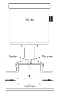
Principle of Operation
- Infrared LED emits light into the media through the sapphire lens
- Receiver measures the amount of light reflected back by particles suspended in the media
- A signal is generated that is proportional to the amount of particles = relative turbidity
- The relative turbidity is based on the Negele calibration standard and is displayed in %TU, NTU or EBC
UL Panel Building Best Practices

Purpose of a Calibration

Process Control – Understanding the Basics

The difference between good control and bad control is the difference between success and failure. Process control begins with understanding your process variables. In manufacturing, teams measure many variables simultaneously, including temperature, flow, and pressure. All of these can be interdependent variables in a single process. Controlling each variable manually would be difficult, time-consuming, prone to mistakes and potentially hazardous. Fortunately, process control simplifies complex tasks, reduces variability and ensures the safety of your workers and equipment.
All process control loops work in the same way, requiring three tasks to occur:
- Measure – measure the right parameters accurately and quickly
- Decide – what to adjust and by how much
- Act – quickly act on the decision before the process goes further out of control.
What is Process Control?
Let’s look at a basic example. A level sensor measures the level in a tank and transmits a signal associated with the level reading to a controller. The controller compares the reading to a predetermined value. If the level is low, the controller sends a signal to the valve on the feed line. The valve opens to add product to the tank and bring the level back to the correct position.
Control loops use many instruments, including transmitters, sensors, valves, and pumps, but always follow three basic steps.
You make good control decisions by applying your process knowledge. For the best response, ‘tune’ the control loop. Too little correction and you have no impact. Too much correction may result in damage to the controls, the equipment or the product.
Let’s define a few other terms commonly used in process control.
- Set Point – the value for a process variable that is desired to be maintained. For example, if a process temperature needs to be kept within ±5°C of 100°C, then the set point is 100°C. Set points can also be maximum or minimum values.
- Error – the difference between the measured variable and the set point. The error can be either positive or negative. In our example, if the measured temperature is 108°C, then the error is +8°C.
Duration – the length of time that an error condition exists - Offset – a sustained deviation of the process variable from the set point. For example, if our control system held the temperature at 100.5°C consistently (even though the set point was 100.0°C), then an offset of 0.5°C exists.
- Load Disturbance – an undesired change in one of the factors that can affect the process variable. For example, the addition of cold water to the tank would be a load disturbance because it lowers the temperature of the process fluid.
- Closed and Open Control Loops –A closed control loop measures a process variable, compares it to a setpoint, and corrects any deviation. An open control loop takes action without considering process conditions.
For example, a system opens a water valve on a preset schedule, regardless of actual process temperature.
ISA Symbols
The Instrumentation, Systems and Automation Society (ISA) is one of the leading process control standards organizations. They have developed a series of symbols for use in engineered drawings and design of control loops.
Piping and Instrumentation Drawings (P&ID) use these symbols to represent measurement instrumentation, controls, piping, equipment and the process variable being measured. Below is a quick reference guide for commonly used symbols:
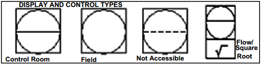
- A circle represents individual measurement instruments, such as transmitters, sensors and detectors. A single horizontal line indicates that the instrument is located in a primary location (i.e. control room). A double line indicates an auxiliary location. No line indicates that it is field-mounted and a dotted line indicates that the instrument is inaccessible (i.e. behind a panel board).

- A square with a circle inside represents instruments that both display readings and perform some control function.
- A hexagon represents computer functions, such as those carried out by a controller.

- A square with a diamond inside represents PLC’s.

- A ‘bow tie’ shape represents a valve in the piping. An actuator is always drawn above the valve to indicate whether it is pneumatic, manual or electric.

- Pumps are represented with this symbol. Directional arrows show the flow direction.

- Piping and connections are represented with several symbols: a heavy line for piping; a thin solid line for process connections to instruments, etc. A full list of piping listings can be found on the ISA site.
- Identification letters indicate the variable being measure (flow, temperature, etc) and the device function (transmitter, sensor, valve, etc). The tag number references the specific control loop.

The figure below is an example of several elements of these symbols being used in a P&ID.

For a complete listing of ISA symbols and identification letters, visit www.isa.org.